2019/01/27

MagicShine MJ-872 PWM filter mod


Backround: 

- Dimming the Magc shine cause a strobing effect especially while skiing in snow.
- Filming with a Gopro or phone camera cause interference in the video/pictures.


Here are some pictures talken from a Google Pixel XL phone. 


100% (no dimming)

Dimming 1

Dimming 2
So during the exposure it seems the light is stopping compleetly 3-4 times.
 

 Opening up

That yellow there is the filter capacitor about 470uF if i recall.

Adding 3000uF in parallel with the original.


Result:

100% ( no change, there is no noise to begin with)
Dim 1
Dim2
Dim3

Some stripes can be seen on the dimming but it is not by far as annoying as the original.
I guess this will address the most of the flicker and interference i see when using in combination with Gopro.
Isolated the capacitors and managed to cram them into the case. But it was a tight squeeze.


2018/10/31

Cheapmondo


Came across the Quasimondo and Cheapmondo circuits to excite transformer/rectifier oscillations and tune in snubber and decided to implement it using junkbox parts:

  • Mosfet: 05N03L
    • Logic level gate
    • Ron 4mohm @4.5Vgs Id=55A
    • Id max 80A
  • "gate driver" 
    • transistor PNP 2N3906
    • basis resistor 1k
    • pulldown 150ohm
  • Clock generator 
    • 74LS14 hex inverter
    • RC feedback
      • 1uF
      • 1kOhm

Simulated in LTspice (using 0.1uF to get higher oscilator freq and lower sim time)
got some LTspice help from:
https://www.mikrocontroller.net/topic/428100 on how to use schmitt trigger in ltspice
http://electronicsbeliever.com/how-to-sweep-resistance-in-ltspice-with-step-by-step-tutorials/ on how to sweep resistor values


Not pretty but it works well :-)


Here is a 500VA toroid oscillating at 1Mhz.
Here it is dampened out. 

2018/10/27

NewClassD NCD1 (re)build. New case and snubber.

Decided to give my aging NewClassD NCD1 a new home. Its been living inside a Doxa 40 Power amp enclosure for 6 years.

I figured i could cram it into a smaller case. I went for the B2109 from Ebay

Had to split the amp alu thermal sink in 2. one on each case heat-sink. I put a 500VA 1x230V 2x36V toroid transformer in there powered trough a 20D thermistor for soft startup. I figured that as normal 500W PC power supplies can live with this in series at all times a ClassD amp might also.  Have no room for a full soft start PCB. The transformer should give me a theoretical Pmax=36V^2/8ohm=162W.


Had some faint noise in the speakers when listening at 50cm. 
Mounted Common mode ferrite filters on power harness into the boards and and on the speaker cable output. Also added ceramic capacitors from speaker terminals to copper tape on lower back chassi. This solved all the hissing noise in the speakers.


Tranformer snubbering

I made a "Quasimondo clone" using stuff in my junkbox. Squarewave generated by 74LS14 and a mosfet that came off a PC mainboard CPU DCDC converter. It is driven with a PNP transistor. and the rest is like the Quasimondo. The exiting works and the transformer rings at 1Mhz.

Here are some results with C_s=150nF Cp=10nF and different R values taken from Rigol DS1054Z. Saved as csv and imported to Libre Office.

Seems 14ohm is the right one. 


Finished 2 channel snubber. One for positive and one for negative supply. 150nF/100V and 10nF/400V film capacitors. Two 30ohm metal film in parallel gives 15ohm. 

2018/03/21

Akai MPK225 in Reason 10

Autodetect surfaces creates 4 surfaces

Reason 10

  • preferences > Control Surfaces 
  • Autodetect surfaces (creates 4 of them)
    • now i can play and tap on the tabs but transport buttons does not work
MPK:
  • Edit button
  • some transport button( play)
  • Change type in the display from MIDI CC to MMC/MIDI
Now the transport start and stop buttons work :-)


Links:
http://community.akaipro.com/akai_professional/topics/im-having-a-hard-time-mapping-my-mpk-225-with-reason-8

Old Emu 1820m PCI on windows 10 desktop


Update 2019-11: After Windows 10 got updated to build 1903 and then it stopped working.
The good news is that there now is a workaround:
https://www.kvraudio.com/forum/viewtopic.php?t=529349


Installed an old EMU 1820m i had in a drawer.

At first it did not work. All LEDs was constantly lit on the external box. Opened up and found 2 blown capacitors i guess at the output of the power supply. Replaced them and now only the correct LEDs light up (like sample rate) and it has connection with the patchmix application.
I got windows sounds but no ASIO in Propellerheads Reason 10.

Stumbled across this:
https://answers.microsoft.com/en-us/windows/forum/windows_10-hardware/e-mu-e-dsp-soundcard-problem-after-installing/0b808069-8356-40b0-9715-e4d392ad5112


  • Turned off computer
  • Removed the card from the PC and booted into windows. 
  • Uninstalled everything EMU/creative.
  • Selected show hidden in device manager and uninstalled the EMU device under audio. 
  • Rebooted. 
  • Downloaded the files for emu 1212m pcie and patchmix for emu 1616m from this:
  • Installed EmuPMX_PCDrv_US_2_30_00_BETA.exe and rebooted
  • Installed EmuPMX_PCApp_US_2_20_00.exe and rebooted
  • Now ASIO E-MU appeared as a card in Reason. Selected it and checked that it sent to ASIO channel 1-2
  • Added Asio strip 1/2 in patchmix and i got sound in my headphones
The emu 1820m is not dead yet :-)


2018/02/12

Start xmr-stak as service in ubuntu

Note to self on how to get xmr-stak working on startup on ubuntu 17.10.

prerequisite: build xmr-stack-cpu

create service folder and copy files from bin folder to it
sudo mkdir /usr/local/xmr
sudo cp * /usr/local/xmr/.

cd /usr/local/xmr/


create start script in /usr/local/xmr

sudo nano server.sh

#!/bin/bash

PID=""

function get_pid {
   PID=`pidof xmr-stak-cpu`
}

function stop {
   get_pid
   if [ -z $PID ]; then
      echo "server is not running."
      exit 1
   else
      echo -n "Stopping server.."
      kill -9 $PID
      sleep 1
      echo ".. Done."
   fi
}


function start {
   get_pid
   if [ -z $PID ]; then
      echo  "Starting server.."
      sysctl -w vm.nr_hugepages=128
      ./xmr-stak-cpu &

      get_pid
      echo "Done. PID=$PID"
   else
      echo "server is already running, PID=$PID"
   fi
}

function restart {
   echo  "Restarting server.."
   get_pid
   if [ -z $PID ]; then
      start
   else
      stop
      sleep 5
      start
   fi
}


function status {
   get_pid
   if [ -z  $PID ]; then
      echo "Server is not running."
      exit 1
   else
      echo "Server is running, PID=$PID"
   fi
}

case "$1" in
   start)
      start
   ;;
   stop)
      stop
   ;;
   restart)
      restart
   ;;
   status)
      status
   ;;
   *)
      echo "Usage: $0 {start|stop|restart|status}"
esac


set permission and make executable
sudo chmod 744 start.sh

prepare service
sudo nano /etc/systemd/system/xmr-stak.service

[Unit]
After=network.target

[Service]
WorkingDirectory=/usr/local/xmr/
Type=forking
ExecStart=/bin/bash server.sh start
Restart=always
User=root

[Install]
WantedBy=multi-user.target


set premission for service
sudo chmod 644 /etc/systemd/system/xmr-stak.service

reload systemctl
sudo systemctl daemon-reload
sudo systemctl enable xmr-stak.service


2018/01/11

Notes on assembling the Micromake C1 "Metal Sheet" version


Because it was confusing and hard to find the links i collect them here for later:

Item bought:
https://www.aliexpress.com/store/product/2017-Micromake-3D-Printer-Micromake-C1-Metal-Sheet-with-H-botXZ-Structure-Large-Printing-Size-245/2128317_32817472147.html?spm=2114.12010612.0.0.3abd18bfJP0XJh

Building instructions for the metal sheet version:
https://drive.google.com/drive/folders/0B1DQUrzkDP-tOVVCaGhFbFRfQjg


Video construction of plastic version: Note that most m4x10 screws should be m4x6 for metal sheet version
https://www.youtube.com/watch?v=TgQI_zN4wcs&list=PLZI4ObifO901p782fvWDsCJt8NQ34NAx_&index=3


Community info, Hard to navigate, but possible to get anwsers:
https://plus.google.com/communities/107601566777965101182/stream/696c3d91-1229-4175-b2ef-3dade8c5ef25


Bottom frame:

Followed the mechanical assembly in the manual:

The first image 2(2).jpg have an error. The 2020 bar is not 360mm but must be 170mm to be able to mount the top 440mm 2020pice at the top later on.

Found out it was better to follow the videos and then check the metal drawings for screw size or other changes in metal version.

Print head

Eccentric nut of print head have a spacer in the wrong location. It must be on the wheel side joining the wheel to make it stack to the correct height like the 2 other wheels.


Print head cooler

Print head is different from the videos and it is missing from the manual:
There is a heat-sink and the extruder tube without cooling.
Here is some discussion and a "missing" part of the manual: https://plus.google.com/photos/photo/112636822015639402104/6498874089418372018?sqid=107601566777965101182&ssid=696c3d91-1229-4175-b2ef-3dade8c5ef25

It looks like the fan is bolted directly on to the alu heatsink supplied. The fan will then keep air from entering the middle of the cooler. Adding some spacers will correct this. I found some longer screws and some M3 nuts and washers to get some space for air between the fan and the cooler. Some M4 nuts acting as spacers.


When mounting the extruder into the cooler hole i put some thermal grease to get better heat transfer to the heat-sink.


Control box

Mains power

In the schematic the power supply input 110V/230V Live and Neutral connected to +- input of control board. instead of the power cord. This is obviously wrong.
https://drive.google.com/drive/folders/0B1DQUrzkDP-tOVVCaGhFbFRfQjg

Also PE (protective earth) is missing so it is probably a good thing to replace the included power cord with one containing PE.

End stops

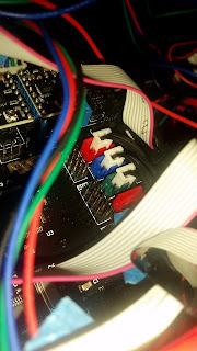
My printer came with 2 pole connectors for end stop but the supplied control board is the Makeboard Pro with 3-pole connectors. 

Modifying the connectors by removing the "locking arrow" on the 2 pole connector makes it fit in the 3 pole slot correctly on the 2 rightmost connection pins.


I connected like it said in the manual but found out that they where wrong.(after a lot of running motors in the wrong direction to the end until the belts slipped and i pulled the power plug)

X-STOP -> X-MAX
Y-STOP -> Y-MAX
Z-STOP -> Z-MAX

Extruder FAN

Connected the extruder fan to green FAN terminal screws. But it did not start. To avoid melting the filament inside the feeder tube i pulled the power and connected the fan directly to 24V. Would be happy if someone can tell if they get the fan automatically starting when the printer starts. 

Heat bed pcb

The heat bead is not even so it probably will not transfer heat to the middle of the glass glass very good. May be necessary to but the clips on the sides instead of the corners. 


PC software

downloaded cura from here (Cura_15.04.0715-C1 Metal Sheet&D1.exe)
https://drive.google.com/drive/folders/0B1DQUrzkDP-tNDU0NXhVcGhlc0k


Result:

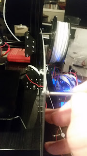
Alligned the bed height as in the video:


Followed this video to print a demo object: https://www.youtube.com/watch?v=Ckfizi-sO7k&list=PLZI4ObifO901p782fvWDsCJt8NQ34NAx_&index=20

Actually the thing works with 1.75 PLA: