Showing posts with label Hack. Show all posts

2019/01/27

MagicShine MJ-872 PWM filter mod


Backround: 

- Dimming the Magc shine cause a strobing effect especially while skiing in snow.
- Filming with a Gopro or phone camera cause interference in the video/pictures.


Here are some pictures talken from a Google Pixel XL phone. 


100% (no dimming)

Dimming 1

Dimming 2
So during the exposure it seems the light is stopping compleetly 3-4 times.
 

 Opening up

That yellow there is the filter capacitor about 470uF if i recall.

Adding 3000uF in parallel with the original.


Result:

100% ( no change, there is no noise to begin with)
Dim 1
Dim2
Dim3

Some stripes can be seen on the dimming but it is not by far as annoying as the original.
I guess this will address the most of the flicker and interference i see when using in combination with Gopro.
Isolated the capacitors and managed to cram them into the case. But it was a tight squeeze.


2013/05/26

HT Projector ground loop isolator

Once I got a projector (Epson EH-TW3200) connected to my surround amplifier I had a problem with hum in the speakers, and some nasty flickers because of bad HDMI signal quality. While connecting the HDMI between the surround amplifier and the projector I noticed a small spark when the metal on the HDMI cable connector came in contact with the metal on the receiver.

The setup with hum:

Projector (Epson EH-TW3200): Grounded
15M HDMI Cable
Surround amp: Not grounded (double isolated)
Media PC: Grounded
Sub: Grounded

I live in a pretty new house with 400V TN (terra neutral) grid. This is common in europe, but not so common in historically in norway.

I tried a small hack with tape on the safety ground on the wall power plug to the projector. Then the problems with flicker and hum went away. But I dont like having disconnected ground for safety reasons so i thought up this ground isolator:

It is pretty ugly, but it will connect the ground during a failure and trigger the earthfault circuit braker in my house. It is basically the same as a Zink Saver used for boats, but they have much more powerful diodes.


Disclaimer, this is most likely a bad idea and will probably kill you and your stereo, but if done correctly it should be better than to disconnect the safety ground completely.

What causes the groundloop in the first place?
The Surround amp/ Sub and PC is sharing the same wall outlet. 
The projetor have another wall outlet with another route to the house star ground point.
The chassi ground of the surround amp and the projector is connected together causing a triangle loop. When there is a potential difference of say 50mV between the ground in the two sockets there will flow current in the screen of the HDMI. I assume the resistance in the HDMI screen to be 0.1 Ohm. Then there will be 50mV/0.1Ohm = 500mA current flowing in the HDMI screen and into the surround receiver and adding noise to all analog logic referenced to this ground (like my Sub)
Adding the isolator the grounds must be more than 1-1.2V appart before there can be flowing any current in the HDMI cable. This will cover most noise and fields the groundloop can be subjected to.


2013/05/23

Mounting a micro switch in the Eumig Mark 610D for synced telecine.


Someone on vimeo asked where I mounted the micro switch inside the 610D projector. 

Here are some pictures :-)
First off, i kept the big ALU part that locks the gear mechanism. It is held at fixed position (6 fps) with some pressure from the steel plate in the top of the first picture. I just rotate this plate to press inn the big alu gear part.

The mounting bracket for the switch is made of some black metal piece i did not need joned to strip of aluminium by a M3 screw and nut and then bent into position. Some double sided tape on the sidewall of the micro switch is securing it to the aluminium.

 The aluminium is bent into position so that the actuator of the micro switch is touching the metal flap that i noticed was "coming out" at each frame advance.


As for the reliability i managed to transfer 2 reels of 100 meters  and about 12 reels of 15 meters without breakdown of the micro switch.
Hope this is of some use to someone. 

2013/01/30

IR encoder from a ball mouse


I was a bit curious to see how an old mouse worked to be able to use the phototransistors in there for other DIY purposes. This video is shot with an old sony DV camcorder and shows how the IR shadows penetrate the receiver phototransistors.


Here is the video:

The quaderature signal output from the two phototransistors is then something like this:

A: __|--|__|--|__|- 
B: _|--|__|--|__|--


The direction of rotation is determined by the phase difference of the pulses. This would then be the other direction:

A: _|--|__|--|__|--
B: __|--|__|--|__|- 

 Hope this is useful for someone, i have used the phototransistors for this energymeter interface. 

2013/01/07

Arduino Energy Meter Interface

I like to measure stuff. I also like to trend my energy use in the hoouse. I have been thinkin about an interface to my house's energy meter for some time, and how to read it. I also have an Arduino Uno in my drawer that i never have powered up. So this is actually my first Arduino project :-)

Here is my energy meter:
On the left side it says 1000imp/kWh. So i looked at the Infra Red LED in the metal ring using the camera of my phone:


It turns out that in the magnet cicle ther is an IR LED that emit one pulse for each Wh or 1000 pulses per kWh. Of course i must try to read these pulses and calculate the Power :-)

Inside and old ball type computer mouse i found an IR phototransistor:

The photo transistor is the black one reading the rotary encoder pulses. It is a dual device to read quaderature signals so i only need to use the middel one wich is the collector and one of the sides that is an emitter. I noticed that the middle pin of the IR transistors was connected to + on the Electrolytic capacitor and assumed it was Vcc. The other two pins went to the IC in the mouse.

I connected it up with a 5V from the Arduino on the collector and 100k pulldown on the emitter to ground. Used an old USB wire and placed the transistor on the meter:
Here is the schematic:
  
And the real world :)
  Then measured the emitter to ground using my prehistoric oscilloscope:
Scope is set at 1ms/div so the pulse is about 1.5ms long.

Actually it seems pretty imune to the other light sources around.. except remote controls :-o


Calculation:
The energy consumed between each blink is 1[Wh] = 3600 [J] = 3600[Ws]
The power is then P[W]= 3600[J] / t[s]


So i only need to measure the time and then calulate power.

Here is the quick and dirty Arduino sketch to measure time using timer:

I really like the Arduino platform. It really can not be easier.

Result from the in the IDEs built in serial console:
Playing with some halogen lamps and it looks good :)


Next i might try to collect the data some how.

2012/09/22

DIY synced telecine with Eumig Mark 610D and Canon 60D

I have a box full of Super 8mm films from my parrents. This is a 'small' project i have started to get them digitally transferred. I have probably spent several hundred hours finding things out and would like to share some of my findings.

I started to buy a second hand Euming Mark 610D from finn.no (like ebay in norway)

Idea was to modify the 610D to get out a sync pulse every time the film advances in the gate. Transfer frames to a Canon 60D in video mode with sync info saved on the audio track. Use avisynth to extract progressive frames from the videofiles and do stabilisation and noise canceling.

Backlight:
A lot of other sites refer to this link: http://blog.iso50.com/23724/convert-8mm-with-5d-mark-ii/
I tried a similar point source with a small flat led, but could not get even focus, might be bad combination with the lens or something. I got a lot of blooming and fuzz round the edges.
I read videoFred's webpage and saw his diffuse backlight so i tried that. I ended up with a big (9W ?) white power led and a diffusor. I found this on ikea:
It is white and have a pyramid diffusor pattern. I cut out a pice and put it in the euming like this:


Remove Shutterblades and S8 R8 crop:
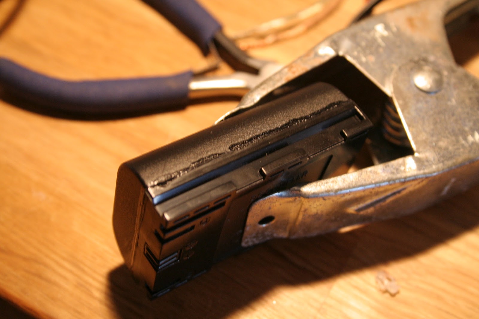
Because i planned to use video function of the 60D i removed the shutterblades. I figured the automatic exposure would have a porblem with it, and also the shutterblades in my Mark 610D run at full speed even with 3 fps film advance. I removed the shutteblades by making a weak spot with a dremel and then jus pry/break them off.


Camera and lens:
I tried at first to mount a Canon 60mm F2.8 on 3 sets of extension tubes and having the camera on a tripod. I was able to fill enough of the DSLR sensor, but there was too much problems with vibrations from the heavy lens so far off my light tripod. Instead i mounted the lens on the projector :-)

I drilled a hole in a storage dustcap for cannon lenses. Mounted it on the 610D with double sided tape. I have borrowed a nice lens: Canon 60mm F2.8. This lens is then projecting the light directly onto the 60D sensor.


On the 60D i only use extension tube to keep out light. I have mounted it on a heavy steel plate from a hardware store and use some M5 bolts and wingnuts to level the plane. I also use a cheap macro slider in between the steel plate and the camera for focusing.


The lens have F2.8, this turned out to be too narrow since i was able to focus on different layers in the film itself. Smaller hole should be able to only let light that have passed prepindicular through the film to enter the lens. And since canon dont have manual apperture i had to improvise:


I have installed a nice firmware hack called Magic Lantern on the 60D. This is a useful tool when transfering films. You get histograms, zebra marks and VU meter while recording. It is magic.

Update: I found it very hard to adjust focus using the camerabody screen. So i connected the HDMI out to a computer monitor with hdmi input. I get very good picture of the 8mm film on the monitor making it easy to adjust focus using the macro slider. When i hit record on the camera body the resolution out of the HDMI port drops to something like old VGA, but then the focus is already good.

Dynamic range:
To be able to capture the dynamic range of the film i have installed a "flat" Picture style in the 60D. I used the one from Marwel: it can be found here: http://marvelsfilm.wordpress.com/2011/01/19/finally-the-new-marvels-cine-profile-3-x-for-canon-dslr/


UPDATE: Sync cable:

I use a cheap condenser microphone parallelled with a microswitch mounted in the projector. The switch will mute the microphone using the normally closed pole. When the film is advanced the sound signal from my noisy room is not shorted and sent to the camera. This fits the Avisynth GetDups plugin perfect as it have a mode to select frames between loud noises. To adjust the sync to not get a frame with film advance i use the shift audio input to GetDups.

Software:

Avisynth
I process the 1080p25 MOV files from the 60D using a script based on videoFred's restoration script . This guy is clever. Check out his website at http://www.super-8.be/.
My version of his script is here:  
http://pastebin.com/Aiu7Zjxx
It is not pretty but it works. Input is 1080p25 video with 6 fps framerate on the Eumig 610D.  Output is 18fps progressive

Virtual Dub
I open the avisynth script in virtual dub, select codec
Cineform Gopro codec ( gets installed together with the software for Gopro)
Select save AVI and then wait. :-)  My computer is able to run the script and encode cineform at 1fps.

Result:
Here is a still from the video after motion stabilization, noisefiltering, colorcorrection, cropping and resize to 1280x720 . It is me and my grandmother may be 1983.
 

As 18 fps is not supported on vimeo i frameblended to 24fps when transcoding to vimeo. 
Pretty pleased with the result. Almost Instagram quality so it should be good enough :P

2012/09/12

Cheap DC power for Canon 60D

I have a small super 8mm setup with my 60D. I got sick of the battery auto power off so I bougth a small "DR-E6" (non Canon) power adapter with AC power brick for my 60D at ebay.
It was dirt cheap and i got a bit suspicious when it said 8.1V on the power brick, and i can accedently connect this thing to one of my 12V DC supplies or even a 11.1V lipo.
So i decided to open the the fake battery adapter to see if it was safe to power from other sources. Inside i found this:
Only a smothing cap 2200uF 16V. Not very safe if i connect something else than the supplied power brick.

I found this in my drawer:  LM2596 based Adjustable DC Step-Down Converter from ebay.
 
Connected it to the power and adjusted the voltage using the smal blue potmeter until it gave me 7,56V:
Loaded it with 10 Ohm power resistor (756mA) and noted that the voltage did not drop much. I also tested with a 12V DC supply and it gave the same result.
Fitted PCB in the battery shell with double sided tape and soldered on the output wires:(the polarity in the pucture turned out to be wrong! Check the polarity on a normal canon battery, i didnt :-/ )
 Put on some hot glue for isolation and cable fixing
O
 Glued togeather with super glue:
I tried it and it did not work. I measeured output voltage on the to slits in the adater and realized i had negative voltage. But the camera survied, i had to open up again and switch the powercable on the pcb. Now it works. :-)
During startup of the camera i get this choice, i have to select 'ok', after that the camera works fine.
 Here you see the cable entry of the 60D body.

 Thats it, i can now power my 60D from anything like car batteries and magicshine battery packs. :-)