
Because it was confusing and hard to find the links i collect them here for later:
Item bought:
https://www.aliexpress.com/store/product/2017-Micromake-3D-Printer-Micromake-C1-Metal-Sheet-with-H-botXZ-Structure-Large-Printing-Size-245/2128317_32817472147.html?spm=2114.12010612.0.0.3abd18bfJP0XJh
Building instructions for the metal sheet version:
https://drive.google.com/drive/folders/0B1DQUrzkDP-tOVVCaGhFbFRfQjg
Video construction of plastic version: Note that most m4x10 screws should be m4x6 for metal sheet version
https://www.youtube.com/watch?v=TgQI_zN4wcs&list=PLZI4ObifO901p782fvWDsCJt8NQ34NAx_&index=3
Community info, Hard to navigate, but possible to get anwsers:
https://plus.google.com/communities/107601566777965101182/stream/696c3d91-1229-4175-b2ef-3dade8c5ef25
Bottom frame:
Followed the mechanical assembly in the manual:
The first image 2(2).jpg have an error. The 2020 bar is not 360mm but must be 170mm to be able to mount the top 440mm 2020pice at the top later on.

Print head
Eccentric nut of print head have a spacer in the wrong location. It must be on the wheel side joining the wheel to make it stack to the correct height like the 2 other wheels.

Print head cooler
Print head is different from the videos and it is missing from the manual:There is a heat-sink and the extruder tube without cooling.
Here is some discussion and a "missing" part of the manual: https://plus.google.com/photos/photo/112636822015639402104/6498874089418372018?sqid=107601566777965101182&ssid=696c3d91-1229-4175-b2ef-3dade8c5ef25
It looks like the fan is bolted directly on to the alu heatsink supplied. The fan will then keep air from entering the middle of the cooler. Adding some spacers will correct this. I found some longer screws and some M3 nuts and washers to get some space for air between the fan and the cooler. Some M4 nuts acting as spacers.

When mounting the extruder into the cooler hole i put some thermal grease to get better heat transfer to the heat-sink.
Control box
Mains power
In the schematic the power supply input 110V/230V Live and Neutral connected to +- input of control board. instead of the power cord. This is obviously wrong.https://drive.google.com/drive/folders/0B1DQUrzkDP-tOVVCaGhFbFRfQjg
Also PE (protective earth) is missing so it is probably a good thing to replace the included power cord with one containing PE.
End stops

My printer came with 2 pole connectors for end stop but the supplied control board is the Makeboard Pro with 3-pole connectors.
Modifying the connectors by removing the "locking arrow" on the 2 pole connector makes it fit in the 3 pole slot correctly on the 2 rightmost connection pins.
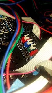

I connected like it said in the manual but found out that they where wrong.(after a lot of running motors in the wrong direction to the end until the belts slipped and i pulled the power plug)
X-STOP -> X-MAX
Y-STOP -> Y-MAX
Z-STOP -> Z-MAX


I connected like it said in the manual but found out that they where wrong.(after a lot of running motors in the wrong direction to the end until the belts slipped and i pulled the power plug)
X-STOP -> X-MAX
Y-STOP -> Y-MAX
Z-STOP -> Z-MAX
Extruder FAN
Connected the extruder fan to green FAN terminal screws. But it did not start. To avoid melting the filament inside the feeder tube i pulled the power and connected the fan directly to 24V. Would be happy if someone can tell if they get the fan automatically starting when the printer starts.
Heat bed pcb
The heat bead is not even so it probably will not transfer heat to the middle of the glass glass very good. May be necessary to but the clips on the sides instead of the corners.
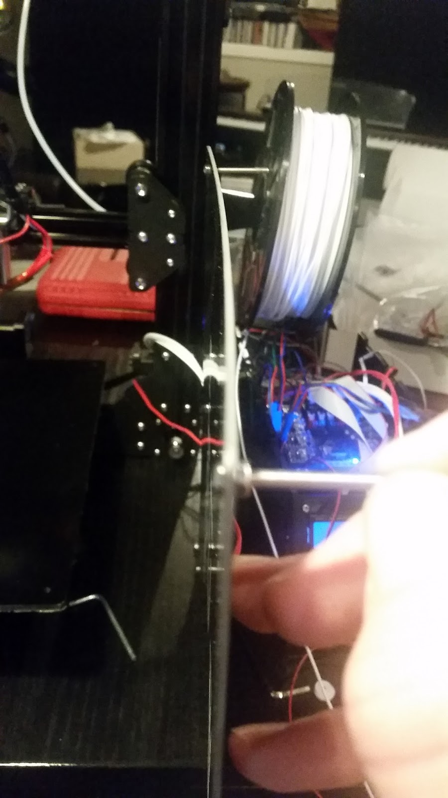
PC software
downloaded cura from here (Cura_15.04.0715-C1 Metal Sheet&D1.exe)https://drive.google.com/drive/folders/0B1DQUrzkDP-tNDU0NXhVcGhlc0k
Result:
Alligned the bed height as in the video:
Actually the thing works with 1.75 PLA: