2018/03/21

Old Emu 1820m PCI on windows 10 desktop


Update 2019-11: After Windows 10 got updated to build 1903 and then it stopped working.
The good news is that there now is a workaround:
https://www.kvraudio.com/forum/viewtopic.php?t=529349


Installed an old EMU 1820m i had in a drawer.

At first it did not work. All LEDs was constantly lit on the external box. Opened up and found 2 blown capacitors i guess at the output of the power supply. Replaced them and now only the correct LEDs light up (like sample rate) and it has connection with the patchmix application.
I got windows sounds but no ASIO in Propellerheads Reason 10.

Stumbled across this:
https://answers.microsoft.com/en-us/windows/forum/windows_10-hardware/e-mu-e-dsp-soundcard-problem-after-installing/0b808069-8356-40b0-9715-e4d392ad5112


  • Turned off computer
  • Removed the card from the PC and booted into windows. 
  • Uninstalled everything EMU/creative.
  • Selected show hidden in device manager and uninstalled the EMU device under audio. 
  • Rebooted. 
  • Downloaded the files for emu 1212m pcie and patchmix for emu 1616m from this:
  • Installed EmuPMX_PCDrv_US_2_30_00_BETA.exe and rebooted
  • Installed EmuPMX_PCApp_US_2_20_00.exe and rebooted
  • Now ASIO E-MU appeared as a card in Reason. Selected it and checked that it sent to ASIO channel 1-2
  • Added Asio strip 1/2 in patchmix and i got sound in my headphones
The emu 1820m is not dead yet :-)


2018/02/12

Start xmr-stak as service in ubuntu

Note to self on how to get xmr-stak working on startup on ubuntu 17.10.

prerequisite: build xmr-stack-cpu

create service folder and copy files from bin folder to it
sudo mkdir /usr/local/xmr
sudo cp * /usr/local/xmr/.

cd /usr/local/xmr/


create start script in /usr/local/xmr

sudo nano server.sh

#!/bin/bash

PID=""

function get_pid {
   PID=`pidof xmr-stak-cpu`
}

function stop {
   get_pid
   if [ -z $PID ]; then
      echo "server is not running."
      exit 1
   else
      echo -n "Stopping server.."
      kill -9 $PID
      sleep 1
      echo ".. Done."
   fi
}


function start {
   get_pid
   if [ -z $PID ]; then
      echo  "Starting server.."
      sysctl -w vm.nr_hugepages=128
      ./xmr-stak-cpu &

      get_pid
      echo "Done. PID=$PID"
   else
      echo "server is already running, PID=$PID"
   fi
}

function restart {
   echo  "Restarting server.."
   get_pid
   if [ -z $PID ]; then
      start
   else
      stop
      sleep 5
      start
   fi
}


function status {
   get_pid
   if [ -z  $PID ]; then
      echo "Server is not running."
      exit 1
   else
      echo "Server is running, PID=$PID"
   fi
}

case "$1" in
   start)
      start
   ;;
   stop)
      stop
   ;;
   restart)
      restart
   ;;
   status)
      status
   ;;
   *)
      echo "Usage: $0 {start|stop|restart|status}"
esac


set permission and make executable
sudo chmod 744 start.sh

prepare service
sudo nano /etc/systemd/system/xmr-stak.service

[Unit]
After=network.target

[Service]
WorkingDirectory=/usr/local/xmr/
Type=forking
ExecStart=/bin/bash server.sh start
Restart=always
User=root

[Install]
WantedBy=multi-user.target


set premission for service
sudo chmod 644 /etc/systemd/system/xmr-stak.service

reload systemctl
sudo systemctl daemon-reload
sudo systemctl enable xmr-stak.service


2018/01/11

Notes on assembling the Micromake C1 "Metal Sheet" version


Because it was confusing and hard to find the links i collect them here for later:

Item bought:
https://www.aliexpress.com/store/product/2017-Micromake-3D-Printer-Micromake-C1-Metal-Sheet-with-H-botXZ-Structure-Large-Printing-Size-245/2128317_32817472147.html?spm=2114.12010612.0.0.3abd18bfJP0XJh

Building instructions for the metal sheet version:
https://drive.google.com/drive/folders/0B1DQUrzkDP-tOVVCaGhFbFRfQjg


Video construction of plastic version: Note that most m4x10 screws should be m4x6 for metal sheet version
https://www.youtube.com/watch?v=TgQI_zN4wcs&list=PLZI4ObifO901p782fvWDsCJt8NQ34NAx_&index=3


Community info, Hard to navigate, but possible to get anwsers:
https://plus.google.com/communities/107601566777965101182/stream/696c3d91-1229-4175-b2ef-3dade8c5ef25


Bottom frame:

Followed the mechanical assembly in the manual:

The first image 2(2).jpg have an error. The 2020 bar is not 360mm but must be 170mm to be able to mount the top 440mm 2020pice at the top later on.

Found out it was better to follow the videos and then check the metal drawings for screw size or other changes in metal version.

Print head

Eccentric nut of print head have a spacer in the wrong location. It must be on the wheel side joining the wheel to make it stack to the correct height like the 2 other wheels.


Print head cooler

Print head is different from the videos and it is missing from the manual:
There is a heat-sink and the extruder tube without cooling.
Here is some discussion and a "missing" part of the manual: https://plus.google.com/photos/photo/112636822015639402104/6498874089418372018?sqid=107601566777965101182&ssid=696c3d91-1229-4175-b2ef-3dade8c5ef25

It looks like the fan is bolted directly on to the alu heatsink supplied. The fan will then keep air from entering the middle of the cooler. Adding some spacers will correct this. I found some longer screws and some M3 nuts and washers to get some space for air between the fan and the cooler. Some M4 nuts acting as spacers.


When mounting the extruder into the cooler hole i put some thermal grease to get better heat transfer to the heat-sink.


Control box

Mains power

In the schematic the power supply input 110V/230V Live and Neutral connected to +- input of control board. instead of the power cord. This is obviously wrong.
https://drive.google.com/drive/folders/0B1DQUrzkDP-tOVVCaGhFbFRfQjg

Also PE (protective earth) is missing so it is probably a good thing to replace the included power cord with one containing PE.

End stops

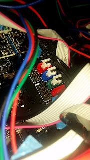
My printer came with 2 pole connectors for end stop but the supplied control board is the Makeboard Pro with 3-pole connectors. 

Modifying the connectors by removing the "locking arrow" on the 2 pole connector makes it fit in the 3 pole slot correctly on the 2 rightmost connection pins.


I connected like it said in the manual but found out that they where wrong.(after a lot of running motors in the wrong direction to the end until the belts slipped and i pulled the power plug)

X-STOP -> X-MAX
Y-STOP -> Y-MAX
Z-STOP -> Z-MAX

Extruder FAN

Connected the extruder fan to green FAN terminal screws. But it did not start. To avoid melting the filament inside the feeder tube i pulled the power and connected the fan directly to 24V. Would be happy if someone can tell if they get the fan automatically starting when the printer starts. 

Heat bed pcb

The heat bead is not even so it probably will not transfer heat to the middle of the glass glass very good. May be necessary to but the clips on the sides instead of the corners. 


PC software

downloaded cura from here (Cura_15.04.0715-C1 Metal Sheet&D1.exe)
https://drive.google.com/drive/folders/0B1DQUrzkDP-tNDU0NXhVcGhlc0k


Result:

Alligned the bed height as in the video:


Followed this video to print a demo object: https://www.youtube.com/watch?v=Ckfizi-sO7k&list=PLZI4ObifO901p782fvWDsCJt8NQ34NAx_&index=20

Actually the thing works with 1.75 PLA:


2016/09/20

Replace cable on AKG K551


I use mostly android phone so the remote shipped on my K551 was not functioning great. I also was not fan of the big jack that would not fit my phone with bumper mounted.

Now that apple decided to remove headphone jack I don't need a reference headphone with apple remote :-)

I recently bought a few new cables from ebay and lunashop.com for my Sennheiser HD590 that included a remote compatible with both android and apple. The Sennheiser have a 2.5mm jack into the phones so i figured i could modify the K551 to the same connector.


Removed the pad

The black cable goes to the other driver. Keep that. De-solder the 3 wires going to the blue cable and remove that.

Solder on a 2.5mm stereo connector. I used this: http://no.rs-online.com/web/p/jack-trs-connectors/5051407/  (RS-online article 505-1407). 

Pin 1 is left, Pin2 is right Pin3 is ground. 


Add some double sided foam tape. (make sure to make a hole in the tape before placing, i didnt and had to do it again) 

Mount the 2.5mm jack and reassemble. 


Very happy with the results. Volume and play pause works nicely. Just set the selector on the back of the remote to android. It even release if cable is pulled to hard.


2016/01/30

Samsung Magician 4.9 Seems to corrupt Gigabyte Z77-D3H Bios

Equipment
Mainboard: Gigabyte Z77-D3H
SSD: Samsung 950 EVO
CPU: i7 3770k
RAM: 16GB
OS: Windows 10 Pro
Graphics: AMD 7900
PSU: Corsair 550W

The problem
Booted into Windows 10
Updated SSD using Samsung Magician 4.9
Magician wants to reboot
When attempting boot there is a black screen and then fans stop after 5 sec, following automatic start again. This boot loop continues 3 times. The 4th time there is a UEFI boot message on the screen. This message freeze and then the reboot cycles starts over again. Keyboard does not respond.

Solution
After reading this:
http://www.tomshardware.co.uk/answers/id-1736983/gigabyte-z77x-ud3h-boot-loop.html

I tried to recover bios holding in power switch in the front of the ATX case while switching on and off the ATX power switch 3 times. Viola it did actually recover the bios to an old version. Now i needed to update the bios again to the latest version.

Conclusion
Don't use Samsung magician to update firmware on Gigabyte Z77 main boards.

2015/12/01

Supra Mains Block MD06-EU/SP MK3


After some problems with HDMI dropouts between my Projector and Receiver i decided to try a "proper" mains filter and surge arrest and a new HDMI cable from supra. Seeing that the HDMI cable alone solved my issues i was curious to see what was in the power strip.

Supra MD06-EU/SP MK3 power strip.

For some reason the manufacturer web page is not showing like it used to so here is the cached one:
http://webcache.googleusercontent.com/search?q=cache:7api80Fi4hsJ:www.jenving.se/products/view/mains-block-md06-eu-sp-mk3-3024000030+&cd=7&hl=no&ct=clnk&gl=no

According to the manufacturer it have

  • a non intrusive filter (NIF) that does not slow down dynamics :-)
  • 3 way protection (Live Neutral and Earth)
  • Dampen noise from from cell phones, dimmers etc
Curious as to what was inside i opened it up :-)


End cap and IEC socket removed. 

Surge protection circuit board

The EMI filter consist of a single turn common mode choke around live and neutral between each outlet.

Ferrite cores in heat shrink tubing between each outlet

As commented in Supra the socket closest to the IEC inlet terminal does not have a filter. When removing the heat shrink on the MOV a thermal fuse reveled itself. 


After what i can see the schematic is like this....i might be wrong.

Comments on the circuit design

  • There is a 10A ceramic fuse in the inlet IEC receptacle on Live, none on Neutral. With schuko there is no lock or indication of what is live and neutral. So the fuse might be on the Neutral line.
  • The filter consist of a single turn common mode choke between the outlet sockets. There is no other filtering element in the design, Not a single capacitor. Differential noise cannot be filtered by this design. Maybe that's why its marketed as a NIF (Non Intrusive Filter).
  • The surge protection is a clamping design built using MOV (metal oxide varistors) in parallel with the main current flow. The clamping deceives are protected against overload using 5A 115C thermal fuses in the same heat shrink as the MOV its protecting. 
  • The Gas filled spark gap conducts if PE deviates more than 470V from the lines during lightning stirkes.
  • A bit surprised to see the LEDs directly in series with resistors across 230V mains. I doubt that normal LEDs have a reverse voltage of that much but the ones used might have a proper avalance spec. A normal diode in antiparalell would not hurt. I really doubt that this design will survive a 2.5kV test voltage after the surge protection fuse is over heated.
  • How can a gaping hole of 43x5cm in the faraday cage block any EMC? Its more like a tin foil hat than a faraday cage.
  • I really like the looks workmanship and the mechanical quality so i will definitely keep it in my system :-)


2015/09/24

Samsung Laptop with Synaptics touchpad in Windows 10


I have struggeled with the synaptics touchpad in my Samsung SF311 laptop since I installed Windows 10 on it. Samsung seems to abandon old hardware with no updated drivers to show for. 

The drivers from synaptics website did show a old style scroll icon as mouse pointer when attempting a scroll but Edge and Explorer windows would not respond.

Having read some attempts that seemed to work on HP laptops with Lenovo drivers I tried to install the Lenovo drivers on my Samsung SF311. The Lenovo drivers works, scrolling and everything! The only culprit now is that it is scrolling the "wrong" direction (up is down and down is up). But this is probably done on purpose to "drag" the page, not a wheel. It actually starts to feel normal.

The drivers I used:
http://support.lenovo.com/us/en/downloads/ds032247
They probably also work on SF411 and SF511 as I guess they share touchpad.

Update: It is possible to reverse direction of scrolling.
Start->Type "Mouse & Touchpad settings"
Device Settings->settings